A 40 - 10 meter QMX
- Dan Koellen AI6XG
- Jun 27, 2024
- 8 min read
Updated: Jul 11, 2024
The QMX from QRP Labs is a small lightweight rig perfect for SOTA, except that it is not offered in a configuration that covers 40 through 10 meters. By sacrificing a few bands and modifying a few filters, I built a QMX that covers my desired bands from 40 through 10 meters. I now have a radio that matches to a 40 meter EFHW for operation on 40, 20, 15, and 10 meters, is able to work local stations as well as dx, and is smaller and lighter weight than the KX2.
Though this build is configured for 40 to 10 meters enough general information is presented so you may build your own configuration. For an unbuilt 20 -10 meter version the steps needed to add 40 meters are outlined in the Conclusions section below.
The QMX
The QMX is a multiband CW (and digital mode) transceiver derived from QRP Labs popular QCX and QDX product lines. It is currently offered, as of the writing of this post, in three configurations: 20 - 10 meters, 60 - 15 meters and 80 - 20 meters. Instead of relying on the Atmel ATMega family of microcontrollers, the QMX utilizes a STM32 microcontroller. The STM32F446 is a 32 bit ARM Cortex M4 microcontroller, much more powerful and capable than the ATMega, enabling more functionality to be built into the QMX.
A very useful feature on the QMX, made possible with the more capable microcontroller, is the virtual USB serial port that allows access to a variety of hardware tests, self diagnosis and configuration menus through terminal access.
The QMX is able to operate on multiple bands by having three low pass filters (LPF) at the transmitter output and four bandpass filters (BPF) at the receiver input. Through the terminal, each band can be configured to use a particular LPF and BPF as shown in figure 1. This feature is used to customize the configuration of the QMX for our desired bands of operation.

For this modification, the 11 meter band is sacrificed with the 40 meter band as a replacement. For 40 meters LPF0 will be built as the standard 40 meter QMX LPF and 20 meters will use LPF1 that is used for 17 and 15 meters in the original configuration. Bandpass filter 3 will be modified for use on 40 meters. The ability of LFP1 to eliminate 20 meter harmonics to satisfy FCC requirements is verified.
It Works!
The modified QMX was used on SOTA summit W7N/WC-005, Chickadee Peak, and successfully activated the peak with 18 contacts. A 40 meter EFHW was used as the antenna, permitting operation in the 40, 20, 15, and 10 meter bands. The rig was powered with a 350 mAh 3s LiPo battery.


Figure 2 The QMX Setup on W7N/WC-005

Figure 3 Contacts Were Made Worldwide During the Activation of W7N/WC-005
QMX Modifications
The basic circuitry and firmware for the QMX is not modified but the configuration of the low pass filters and bandpass filters are changed. When modifying the QMX configuration it is imperative to understand how the performance of the QMX may be affected, and to ensure emissions quality requirements are met.
The QMX that is modified for this post uses revision 2 PCB and initially loaded with version 1_00_017 firmware and later updated to version 1_00_019. The modifications were done on an already built standard 20 - 10 meter version. Configuration changes are easier to do on an unbuilt unit.
Low Pass Filter
The low pass filter (LPF) is used to attenuate harmonics of the carrier, and other spurious signals, to meet emissions quality requirements as well to pass as much of the carrier as possible while providing a match to the 50 Ohm output.
The QMX has three LPFs (figure 4), the appropriate LPF is selected by the device's firmware for a particular band through Q509, Q510 and Q511. The diodes and 47uH inductors are also part of the LPF switching circuit.

The schematic in figure 5 shows the filter components with the switching components removed. The LPF is a third order filter consisting of C1, L1 and C2. It is followed by a third harmonic trap of L2 and C4.

For the QMX, the third harmonic is most important harmonic to attenuate. The push pull class D configuration of the power amplifier produces very low levels of even harmonics, including the second harmonic. The LPF is simulated using AE6TY's excellent SimNEC program with the standard 20 meter LPF values (figure 6a and 6b). The passband is flat with rolloff starting just below the 17 meter band. The second harmonic, in the 10 meter band, is only attenuated about 22dB. But the low level of second harmonic generation makes this adequate to meet the FCC emission regulation of -43dBc. The action of the third harmonic trap is evident by the deep trough at 42 MHz, provided more than enough attenuation to meet FCC emission standards.


The configuration of my base QMX (figure 1) uses this LPF0 for 20 meters with 17 and 15 meters sharing LPF1 and 12, 11 and 10 meters sharing LPF2. I decided to eliminate 11 meters and insert the parameters for 40 meters in that slot. But there was no LPF available that would adequately attenuate 40 meter harmonics, as concluded from the simulation of LPF0 (20 meters) in figure 6a.
Since the unit was already built with the 20 meter filter as LPF0, I considered adding capacitors to each capacitor to bring the capacitance to that specified for a QMX 40 meter LPF, while maintaining the 20 meter inductors. This was simulated (figure 7) and shown to reduce the harmonics to some degree, potentially pass the FCC emission requirements. But it also reduced 20 meter power by 10dB. In addition I wanted to attenuate 40 meter harmonics more aggressively since 40 meter harmonics appear in the 20, 15 and 10 meter bands. This configuration is not used for 40 meter LPF.

40 Meter Low Pass Filter
The 40 meter LPF specified for a QMX build was simulated and shown in figure 8a and 8b. The attenuation of the harmonics is more aggressive and conform to FCC emission requirements.


Since LPF0 was already configured for 20 meters the two inductors were removed and replaced with the inductors specified for 40 meters. The removal was not too difficult using a 4 mil conical soldering tip, a decent solder sucker and solder flux. The 40 meter inductors are wound on T30-6 toroids rather than the T30-2 toroids used for the 20 meter LPF. Capacitors were soldered across the existing 20 meter LPF capacitors to bring the values to those required for the 40 meter LPF (figure 9). Surface mount capacitors were used, both 1206 and 0805 capacitors were used. My preference were 0805 capacitors. Table 1 shows the values used for the inductors and the added capacitors. If you are building from scratch then just use the components as designed for 40 meters.


20 Meter Low Pass Filter
Low pass filter LFP1 will be used for 20 meters in addition to its as-built assignment to 17 and 15 meters. Simulation (figure 9) shows that attenuation at the second and third harmonic should be enough to meet FCC emission requirements. QRP Labs has data showing that the third harmonic is ~ -10dBc before the low pass filter. Figure 10 shows attenuation is >10dB at the second harmonic and 40dB at the third harmonic. The expectation would be better than -50dBc for the 20 meter third harmonic.

Low Pass Filter Evaluation
After changing LFP0 to 40 meter design values and changing band configuration to use LFP1 for 20 meters, the performance of the low pass filters was evaluated. The harmonic content was measured for both 40 and 20 meters using a TinySA Ultra with 60dB of external attenuation as shown figure 11.

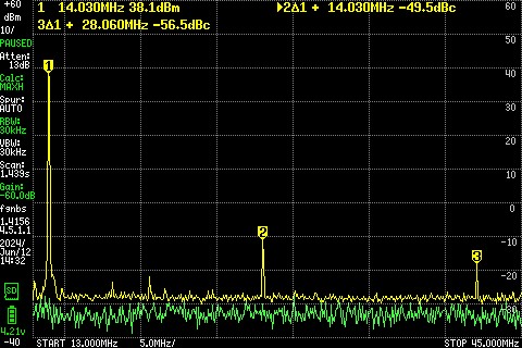

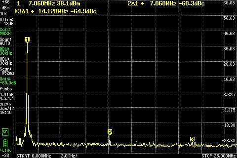
Figure 11 Harmonic Content for 20 meters and 40 meters
Forty meter harmonics are reduced to very low levels, easily exceeding FCC emission regulation. The second harmonic for twenty meters is -49.5dBc and third harmonic is -56.5dBc, both exceeding FCC emission regulations.
Since 20 meters is not using the intended LPF, the builder must demonstrate conformance to emission regulations before using the radio on 20 meters.
Bandpass Filters
There are four bandpass filters (BPF) in the QMX that are switched in for a particular band according to the band configuration setup (figure 1). Looking at figure 12, L401 is a tapped inductor in series with a capacitor that is selected by the 74CBT3253 analog switch. The selected Y input is connected to the W output which feeds the input phasing transformer T401. Being a simple series LC filter, it has a fairly wide bandwidth. This enables a BPF to be shared between bands, e.g. 20 and 17 meters share BPF3.

BPF3 Modification
In the standard configuration, 20 and 17 meters share BPF3 which is all the L401 windings in series with C402. Figure 13 shows BPF3 response for 40, 20 and 17 meters using the QMX RF Filter Hardware Test.


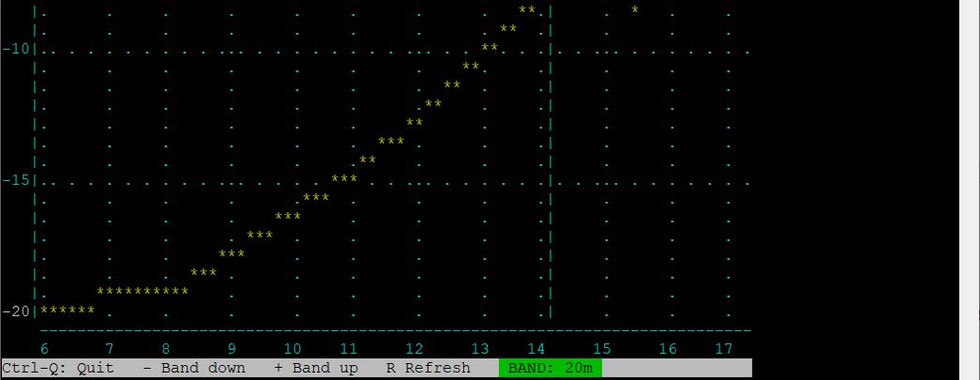


Figure 13 BPF3 Response as-built for 40, 20 and 17 meters
From figure 13 the peak of BPF3 is about 18MHz in the as-built configuration. This works adequately for 20 and 17 meters as designed but attenuates the 40 meter signal significantly. To provide better performance for 40 meters the peak frequency of BPF3 needs to be made lower. According to simulation, adding 100pF to the already installed C402 56pF should lower the peak frequency to about 11MHz. I found that adding 150pF instead, for a total of 206pF, provides good results; there is no change to L401. The resulting BPF3 test results are shown in figure 14.


Figure 14 BPF3 Response for 40, 20 and 17 meters After Modification
Receiver Test
The Minimum Discernible Signal (MDS) test was used to determine the sensitivity of the QMX for all bands before and after modification of BPF3. The MDS tests were completed using an Elecraft XG3 RF Signal Source and an Agilent U1232A True RMS DMM, using the procedure outlined in the XG3 manual. As seen in figure 15, the 40 meter sensitivity was improved with the BPF3 modification as compared to the as-built configuration. The other bands had little significant change. After testing it was decided to move 17 meters to BPF2 which helped sensitivity results. Overall the sensitivity of the QMX is very good on all bands.

Conclusions
By modifying the LPF and BPF configuration of the QMX, 40 meters operation can be added to a high band version. This requires losing two bands: 11 meters and 30 meters. Modifications are easier to do on a unit that has not been assembled but not too difficult on an already built unit. The final Band Configuration is shown in figure 16.
If you are starting with an unbuilt 20 - 10 meter kit there are just a few steps to add 40 meters to your radio. Build LFP0 as a 40 meter LFP as in the low or mid band kits; table 1 is also a guide. Substitute a 210pF capacitor for C402. And then configure your QMX as in figure 16. There will likely be a difference in LPF performance due to variation in winding of the toroids, the toroid's material characteristics variance and capacitor variance. With this in mind and since the 20 meter output is not using the intended LPF, you must confirm compliance to emission quality requirements.
Or try your own modifications using a similar process as outlined in this post. No matter what configuration you may decide to build, checking receiver sensitivity is recommended and confirming compliance to emission quality requirements is mandatory.
Good Luck and have fun with the QMX.

Acknowledgements and References
Many thanks to Bill, N6MTB, for sharing his midband QMX modifications which inspired this project.
QMC Assembly Manual rev. 2
QMX Operation Manual 1_00_018